History of USB Flash drives
 The first USB flash drive was manufactured in early 2000 by a company called Trek with product Thumbkey®, shortly followed by M-systems (now SanDisk) with their DiskonKey® drive.
Many companies claim to have been first to develop the USB Flash drive which resulted in many patent disputes over the years.
With time USB flash drives have taken on other forms than the classic memory stick and have been integrated into USB pens and USB mouse or have been integrated into creative casings of customised USB drives.
Adoption is widespread as the cost for USB drives has dramatically decreased and are now a very cost effective way to easily store and transport data files. These data files can be of any sort ranging from simple text to audio over to picture and video files.
 USB Flash drives, also known as USB pen drives and Memory sticks are increasingly common in the world and the digital storage device of choice.Version history
- USB 1.0: Released in January 1996.
Specified data rates of 1.5 Mbit/s (Low-Bandwidth) and 12 Mbit/s (Full-Bandwidth). Does not allow for extension cables or pass-through monitors (due to timing and power limitations). Few such devices actually made it to market. - USB 1.1: Released in August 1998.
Fixed problems identified in 1.0, mostly relating to hubs. Earliest revision to be widely adopted
USB 2.0: Released in April 2000.
Added higher maximum bandwidth of 480 Mbit/s (60 MB/s) (now called "Hi-Speed"). Further modifications to the USB specification have been done via Engineering Change Notices (ECN). The most important of these ECNs are included into the USB 2.0 specification package available from USB.org:
- Mini-A and Mini-B Connector ECN: Released in October 2000.
Specifications for Mini-A and B plug and receptacle. Also receptacle that accepts both plugs for On-The-Go. These should not be confused with Micro-B plug and receptacle. - Errata as of December 2000: Released in December 2000.
- Pull-up/Pull-down Resistors ECN: Released in May 2002.
- Errata as of May 2002: Released in May 2002.
- Interface Associations ECN: Released in May 2003.
New standard descriptor was added that allows multiple interfaces to be associated with a single device function. - Rounded Chamfer ECN: Released in October 2003.
A recommended, compatible change to Mini-B plugs that results in longer lasting connectors. - Unicode ECN: Released in February 2005.
This ECN specifies that strings are encoded using UTF-16LE. USB 2.0 did specify that Unicode is to be used but it did not specify the encoding. - Inter-Chip USB Supplement: Released in March 2006.
- On-The-Go Supplement 1.3: Released in December 2006.
USB On-The-Go makes it possible for two USB devices to communicate with each other without requiring a separate USB host. In practice, one of the USB devices acts as a host for the other device. - Battery Charging Specification 1.1: Released in March 2007 (Updated 15 Apr 2009).
Adds support for dedicated chargers (power supplies with USB connectors), host chargers (USB hosts that can act as chargers) and the No Dead Battery provision which allows devices to temporarily draw 100 mA current after they have been attached. If a USB device is connected to dedicated charger, maximum current drawn by the device may be as high as 1.8 A. (Note that this document is not distributed with USB 2.0 specification package only USB 3.0 and USB On-The-Go.) - Micro-USB Cables and Connectors Specification 1.01: Released in April 2007.
- Link Power Management Addendum ECN: Released in July 2007.
This adds a new power state between enabled and suspended states. Device in this state is not required to reduce its power consumption. However, switching between enabled and sleep states is much faster than switching between enabled and suspended states, which allows devices to sleep while idle.
| The standard USB A plug (left) and B plug (right) | |||
| Pin 1 | VCC (+5 V) | ||
|---|---|---|---|
| Pin 2 | Data- | ||
| Pin 3 | Data+ The Micro-USB interface is commonly found on chargers for mobile phones | ||
| Pin 4 | Ground | ||

The Micro-USB interface is commonly found on chargers for mobile phones
Specified with a maximum transmission speed of up to 5 Gbit/s (640 MB/s), which is over 10 times faster than USB2.0 (480 Mbit/s), although this speed is typically only achieved using powerful professional grade or developmental equipment. USB 3.0 reduces the time required for data transmission, reduces power consumption, and is backward compatible with USB 2.0. The USB 3.0 Promoter Group announced on 17 November 2008 that the specification of version 3.0 had been completed and had made the transition to the USB Implementers Forum (USB-IF), the managing body of USB specifications.[9] This move effectively opened the specification to hardware developers for implementation in future products. A new feature is the "SuperSpeed" bus, which provides a fourth transfer mode at 5.0 Gbit/s. The raw throughput is 4 Gbit/s (using 8b/10b encoding), and the specification considers it reasonable to achieve around 3.2 Gbit/s (0.4 GB/s or 400 MB/s), increasing as hardware advances in the future take hold.
A flash drive, a typical USB mass-storage device
How To Use USB As Input/Output?
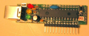
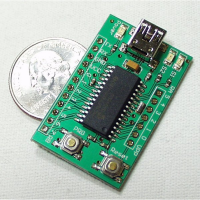
The UBW board is a small board that contains a Microchip PIC USB-capable microcontroller, headers to bring out all of the PICs signal lines (to a breadboard for example), only costs about $15-$20 to build and is powered from the USB connection. I designed this board to be a simple parallel port replacement tool for Bruce Shapiro for use in his bits-to-bytes-to-bots class. Apologies to all other 'Whacker' projects like EDTP's Packet Whacker for stealing a great name . All tools used to design this project are free, and the design is open to anyone to use for whatever they wish. Please build your own and improve upon it!


FireWire USB was originally seen as a complement to FireWire (IEEE 1394), which was designed as a high-bandwidth serial bus which could efficiently interconnect peripherals such as hard disks, audio interfaces, and video equipment. USB originally operated at a far lower data rate and used much simpler hardware, and was suitable for small peripherals such as keyboards and mice.
The most significant technical differences between FireWire and USB include the following:
- USB networks use a tiered-star topology, while FireWire networks use a tree topology.
- USB 1.0, 1.1 and 2.0 use a "speak-when-spoken-to" protocol; peripherals cannot communicate with the host unless the host specifically requests communication. USB 3.0 allows for device-initiated communications towards the host. A FireWire device can communicate with any other node at any time, subject to network conditions.
- A USB network relies on a single host at the top of the tree to control the network. In a FireWire network, any capable node can control the network.
- USB runs with a 5 V power line, while Firewire in current implementations supplies 12 V and theoretically can supply up to 30 V.
- Standard USB hub ports can provide from the typical 500 mA/2.5 W of current, only 100 mA from non-hub ports. USB 3.0 and USB On-The-Go supply 1.8 A/9.0 W (for dedicated battery charging, 1.5 A/7.5 W Full bandwidth or 900 mA/4.5 W High Bandwidth), while FireWire can in theory supply up to 60 watts of power, although 10 to 20 watts is more typical.
Ethernet
The IEEE 802.3af Power over Ethernet (PoE) standard has a more elaborate power negotiation scheme than powered USB. It operates at 48 V DC and can supply more power (up to 12.95 W, PoE+ 25.5 W) over a cable up to 100 meters compared to USB 2.0 which provide 2.5 W with a maximum cable length of 5 meters. This has made PoE popular for VoIP telephones, security cameras, wireless access points and other networked devices within buildings. However, USB is cheaper than PoE provided that the distance is short, and power demand is low.Ethernet standards requires electrical isolation between the networked device (computer, phone, etc.) and the network cable up to 1500 V AC or 2250 V DC for 60 seconds.[70] USB has no such requirement as it was designed for peripherals closely associated with a host computer, and in fact it connects the peripheral and host grounds. This gives Ethernet a significant safety advantage over USB with peripherals such as cable and DSL modems connected to external wiring that can assume hazardous voltages under certain fault conditions.[71]
Digital musical instruments
Digital musical instruments are another example of where USB is competitive for low-cost devices. However Power over Ethernet and the MIDI plug standard are preferred in high-end devices that must work with long cables. USB can cause ground loop problems in equipment because it connects the ground wires on both transceivers. By contrast, the MIDI plug standard and Ethernet have built-in isolation to 500 V or more.eSATA/eSATAp
The eSATA connector is a more robust SATA connector, intended for connection to external hard drives and SSDs. It has a far higher transfer rate (3 Gbit/s or 6 Gbit/s, bi-directional) than USB 2.0. A device connected by eSATA appears as an ordinary SATA device, giving both full performance and full compatibility associated with internal drives.eSATA does not supply power to external devices. This is an increasing disadvantage compared to USB. Even though USB's 2.5 W is sometimes insufficient to power external hard drives, technology is advancing and external drives gradually need less power, exacerbating the eSATA disadvantage. eSATAp (power over eSATA; aka ESATA/USB) is a connector introduced in 2009 that supplies power to attached devices using a new, backwards-compatible, connector. On a notebook eSATAp usually supplies only 5 V to power a 2.5 in HDD/SSD; on a desktop workstation it can additionally supply 12 V to power larger devices including 3.5 in HDD/SSD and 5.25 in optical drives.
eSATAp support can be added to a desktop machine in the form of a bracket connecting to motherboard SATA, power, and USB resources.
eSATA, like USB, supports hot plugging, although this might be limited by OS drivers and device firmware.


PrereleasesUSB 1.0
No comments:
Post a Comment